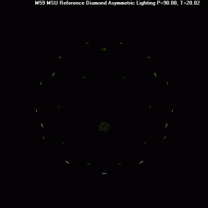
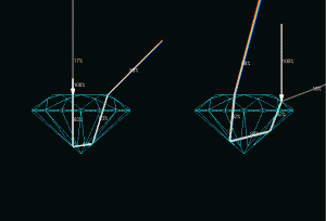
shape
carat
color
clarity

AGS new cut grade system early 2005

Status
Not open for further replies. Please create a new topic or request for this thread to be opened.

adamasgem

Brilliant_Rock
Joined
May 23, 2003
Messages
1,338
----------------
On 10/9/2004 7:52:00 AM Serg wrote:

re:Do you mean glare, If you do there is no chromatic flare from glare.

Main flashes after 4 'refractions' could have much bigger intensity. Yes, I ask about first reflection( 0 refraction), and first reflection should gray( although reflectivity factor depends from wave-length .
1.gif
)


I agree, that's why there is no "flare" from the glare, angle of reflection = angle of incidence, independent of wavelength, and it should "gray". I agree.. The plotted position of the "first reflection" is again a function of the position and angle of incidence

re:As to your meaning of 'first reflection', the results are dependent on the point of incidence on the stone.

Please use same algorithm for this test.

Why do you want use special algorithm for first reflection?----------------


I don't understand your question regarding "special algorithm". All internal paths are processed with the same algorithm in my software.

The "problem" is that we have to define the same input conditions, that is why I suggest using the centroids of the facets and a POINT source (spot with no area) which will then fix the angle of incidence to each facet.


On another note, I've looked at removing the "non-flare" refractions from any metric for flare. What I mean is that to be counted towards a metric for "chromatic flare", there MUST BE two or more physically adjacent and unbroken points of color, from sequential wavelengths) coming from the same incident ray. I.E. a spectrum from > is a flare while a sequence > is not counted as "flare" even though it might resolve in a composite "picture" as looking like a "flare".

Also ,one of the problems I mentioned before, is the ambiguity created when a ray randomly hits (near) a facet junction, which facet is it reflecting from, given the numerics of the problem. You have to make that decision in the software by defining constraints and tolerances for picking one facet over another.
 

Serg

Ideal_Rock
Trade
Joined
Mar 21, 2002
Messages
2,631
Re:I don't understand your question regarding "special algorithm". All internal paths are processed with the same algorithm in my software.

The "problem" is that we have to define the same input conditions, that is why I suggest using the centroids of the facets and a POINT source (spot with no area) which will then fix the angle of incidence to each facet.


Do you use centroids of the facets for rays in previous your images?

If yes, what parameters are defined by Monte Carlo method? ( Point of light source and centroids of the facets define all your rays in this case)
 

adamasgem

Brilliant_Rock
Joined
May 23, 2003
Messages
1,338
----------------
On 10/9/2004 1:23:37 PM Serg wrote:

Re:I don't understand your question regarding 'special algorithm'. All internal paths are processed with the same algorithm in my software.

The 'problem' is that we have to define the same input conditions, that is why I suggest using the centroids of the facets and a POINT source (spot with no area) which will then fix the angle of incidence to each facet.


Do you use centroids of the facets for rays in previous your images?

No I did not, I used a uniformly distributed random selection of a point within a 4mm circle 600mm away from the diamond to define starting point coordiantes pt, and projected a ray to a uniformly distributed point on the crown, random selection of the facet based on relative area of each facet and uniform distribution within facet for ending incident point r0

If yes, what parameters are defined by Monte Carlo method? ( Point of light source and centroids of the facets define all your rays in this case)

Monte carlo selection of pt and r0 defines a direction vector for the light ray U; where U = r0 - pt ;
The angle of incidence is defined relative to the facet containing the point r0

What I was suggesting is that somehow we define a scenario we can both run, to compare the results of your backward ray(beam) trace to my much slower forward Monte Carlo methodology.

I'll gin up some examples, right now I'm running 20000 rays (times 30 wavelengths) with a hemispherical illumination, which of course will generate a fairly white "flare" picture. When that finishes (takes about 6 hours I guess, I'll save the individual facet class pictures. I'm trying to define a scaler metric for Fire which makes sense to me, which is the weighted(cosine squared) and unweighted integration of color intensity for unbroken "flares", much like GIA did in their DCLR metric.

By unbroken flares I mean any sequence of colors (at every 10 nm) that group and are generated by the same incident ray U at a sequence of wavelengths e.g. . If we have a solitary point of color generated by a ray, then it is not considered a flare. A "flare" may be "broken", if because of differing paths as a function of wavelength they don't emerge in the "same" are to form a "spectrum" or part thereof.


----------------
 

Serg

Ideal_Rock
Trade
Joined
Mar 21, 2002
Messages
2,631
re: "No I did not, I used a uniformly distributed random selection of a point within a 4mm circle 600mm away from the diamond to define starting point coordiantes pt, and projected a ray to a uniformly distributed point on the crown, random selection of the facet based on relative area of each facet and uniform distribution within facet for ending incident point r0"

Why do not you use same uniformly distribution for first reflection? It should work very fast, because you need calculate only first reflection/
If you do not like to publish such image I do not know how we can easy find reason of difference between our images.
 

adamasgem

Brilliant_Rock
Joined
May 23, 2003
Messages
1,338
----------------
On 10/11/2004 9:54:43 AM Serg wrote:

re: 'No I did not, I used a uniformly distributed random selection of a point within a 4mm circle 600mm away from the diamond to define starting point coordiantes pt, and projected a ray to a uniformly distributed point on the crown, random selection of the facet based on relative area of each facet and uniform distribution within facet for ending incident point r0'

Why do not you use same uniformly distribution for first reflection? It should work very fast, because you need calculate only first reflection/

I don't presently plot that in the software.They will be of littel use as all they will show is the average facet angles I used (which is what you defined) and average variation about the mean facet angle due to the diameter and position of the spot and the diameter of the stone.

If you do not like to publish such image I do not know how we can easy find reason of difference between our images.

How about FIXING the input ray starting point to (0,0,600mm) and the impact point to the centroid of each facet as I suggested?

----------------

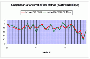
On another note, I applied my "average, WLR weighted, unbroken flare" Chromatic Flare metric definition and ran 1000 parallel input rays (like GIA model) to the 28 stones that GIA defined in their Fire article (RD01-RD29) just as a sanity check and normalized the results. I would note that 1000 random positioned parallel rays is propably too small a sample size for accurate comparison purposes, but here are the results, which seem pretty good, to me at least
1.gif


metric.gif
 

Serg

Ideal_Rock
Trade
Joined
Mar 21, 2002
Messages
2,631
re:I don't presently plot that in the software.They will be of littel use as all they will show is the average facet angles I used (which is what you defined) and average variation about the mean facet angle due to the diameter and position of the spot and the diameter of the stone.

Marty,

I am sure we should start verification our images from such simple test.
I published such our image on PS.

If you do not do same and have not any other more strategy for verification result I do not like continue this discussion this you. noneffective work is not reasonable for me.
Bye-bye.
 

adamasgem

Brilliant_Rock
Joined
May 23, 2003
Messages
1,338
----------------
On 10/11/2004 12:39:24 PM Serg wrote:

re:I don't presently plot that in the software.They will be of littel use as all they will show is the average facet angles I used (which is what you defined) and average variation about the mean facet angle due to the diameter and position of the spot and the diameter of the stone.

Marty,

I am sure we should start verification our images from such simple test.
I published such our image on PS.

If you do not do same and have not any other more strategy for verification result I do not like continue this discussion this you. noneffective work is not reasonable for me.
Bye-bye.----------------


Well Sergey Don't get upset. I was trying to find out if you could easily do what I had suggested..
Here is glare for 10000 random input ray on 6mm diamond, for your MSU defined diamond angle, 4mm spot centered over diamond 600mm over stone

glare.jpg
 

adamasgem

Brilliant_Rock
Joined
May 23, 2003
Messages
1,338
----------------
On 10/11/2004 12:39:24 PM Serg wrote:

re:I don't presently plot that in the software.They will be of littel use as all they will show is the average facet angles I used (which is what you defined) and average variation about the mean facet angle due to the diameter and position of the spot and the diameter of the stone.

Marty,

I am sure we should start verification our images from such simple test.
I published such our image on PS.

If you do not do same and have not any other more strategy for verification result I do not like continue this discussion this you. noneffective work is not reasonable for me.
Bye-bye.----------------


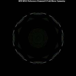
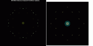
Here are flares (4 internal facet interactions allowed) from 300 rays along with the glare for that run, for the MSU diamond and spot definition.
I spent 3 hours or so modifying my software to get the simultaneous glare and flare plots..

Will you play nice now and comment.
1.gif
Is the difference because you are using a backwards ray trace for your presentations?

M59comp.gif
 

Serg

Ideal_Rock
Trade
Joined
Mar 21, 2002
Messages
2,631
RE:"Will you play nice now and comment. Is the difference because you are using a backwards ray trace for your presentations?"

Marty,

Now I neatly see a number of reasons why our images are different.

1. You use very small size of the sphere (about 10mm). At the same time I indicated that I use 1000mm and repeatedly asked to indicate your sphere size. Reflection from the table at your sphere occupies all central part of the sphere, but on my earlier published pictures the reflection of the table occupies tiny part of the sphere. So it is practically impossible to compare these pictures for human.
2. The fact that at your picture the intensity of flashes from Girdle Upper Facets is more stronger than from the table and from other facets. There is difference of intensities in several times on my monitor, though it should be about 10%. See http://www.cutstudy.com/3dbook/eng/crypted/dif.html
This confirms that either you have mistake in RayTracing algorithm or you incorrectly determine the density of points distribution by MonteCarlo method for incline facets, or this is appeared already at the stage of projection of the sphere to the plane (points density on the sphere inadequately reflects real intensity because it is incorrectly considered under projection of the sphere to the plane).

Also
- It is seen some radial structure in location of the points on the table. Possibly this is accidental event.
- Most likely you don't use gamma correction.

I suggest you to make corresponding changes to your program before we continue comparison.
 

adamasgem

Brilliant_Rock
Joined
May 23, 2003
Messages
1,338
----------------
On 10/12/2004 6:23:03 AM Serg wrote:

RE:'Will you play nice now and comment. Is the difference because you are using a backwards ray trace for your presentations?'

Marty,

Now I neatly see a number of reasons why our images are different.

1. You use very small size of the sphere (about 10mm). At the same time I indicated that I use 1000mm and repeatedly asked to indicate your sphere size. Reflection from the table at your sphere occupies all central part of the sphere, but on my earlier published pictures the reflection of the table occupies tiny part of the sphere. So it is practically impossible to compare these pictures for human.

OK, I guess I see what you are talking about. My screen hemisphere is scaled to +/- the diameter of the stone and I'm projecting to a hemisphere of 0.5 the diameter. (Good observation!!!) And your screen is scaled to 1000mm (167 diameters) so your x,y position is 1000*sin()/167*d or 6*sin/d vs my 0.5*sin()/2*d or 0.25*sin(), I can make that change


2. The fact that at your picture the intensity of flashes from Girdle Upper Facets is more stronger than from the table and from other facets. There is difference of intensities in several times on my monitor, though it should be about 10%. See http://www.cutstudy.com/3dbook/eng/crypted/dif.html

My intensities are cummulative and a function of the pixilization


This confirms that either you have mistake in RayTracing algorithm or you incorrectly determine the density of points distribution by MonteCarlo method for incline facets, or this is appeared already at the stage of projection of the sphere to the plane (points density on the sphere inadequately reflects real intensity because it is incorrectly considered under projection of the sphere to the plane).

SOunds like it is the scaling differences

Also
- It is seen some radial structure in location of the points on the table. Possibly this is accidental event.

If you are refereing to the glare picture it might be due to the algorithm used for selection of spot or facet projection points. I use a random radial position within a 1% annular ring to get a quasi uniform selection of points on the spot, I can always make it finer quantization.

- Most likely you don't use gamma correction.

You are right there, I haven't used the gamma lookup curve for RGB, easy change, another slow down
1.gif


I suggest you to make corresponding changes to your program before we continue comparison.----------------
Fine by me, will get back to you, Thanks Sergey
 

adamasgem

Brilliant_Rock
Joined
May 23, 2003
Messages
1,338
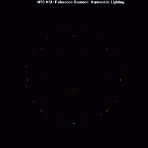
Now we are getting better
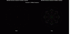
1.gif
gif conversion from bmp using paint
Projection to 1000mm and using probably wrong gammas

I haven't paid much attention to the gamma correction, I checked my monitor control file, and I've most probably got the wrong gammas in for my LCD screen. The RGB gammas that were in my file were ( 2.2312, 2.2567, 2.2312)
I think I tried using a pantone caqlibrator once on my LCD screen, and I don't think it worked too well

The defaults in my software are 2.22, and the user can recalibrate

M59_1kc.gif
 

adamasgem

Brilliant_Rock
Joined
May 23, 2003
Messages
1,338
I forgot to add that the prevous picture was generated for 100 random positioned rays, so I may or may not have generated the same flares that you have in the center of the diagram.. I think that will make a difference..
 

Serg

Ideal_Rock
Trade
Joined
Mar 21, 2002
Messages
2,631
Good.

Resemblance of our images is much better now.

I suggest do more tests for first reflection.

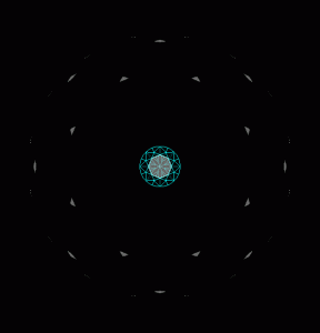
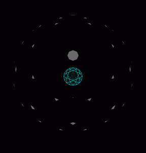
Sphere radius=20mm.

Second image has tilt 20 degree.

Could you use 500-1500 rays. I hope it is fast for first reflection

FirstReflectionSphere20.gif
 

adamasgem

Brilliant_Rock
Joined
May 23, 2003
Messages
1,338
Since since my coordinate frames are set up so I don't normally rotate the stone I rotated the spot about 20 degrees with respect to the stone but also
and had to also change the projection perspective. Does your hemisphere rotate with the stone or stay fixed with respect to the stone..

20degcen1.gif
 

adamasgem

Brilliant_Rock
Joined
May 23, 2003
Messages
1,338
sergey Finnally got the coordinate rotations sorted out so I'm consistent with your offset spot (tilted stone) I believe. I can only do one spot at a time (or effectively tilt stone for with respect to the one spot), but will add multiple spot capability later..

2020fix.gif
 

Serg

Ideal_Rock
Trade
Joined
Mar 21, 2002
Messages
2,631
Marty,

I think that the problem of big difference of flash brightness's from the table and Main facet is not connected with RayTracing. The brightness strongly depends on the angle between direction of sphere observation and perpendicular to facet (the brightness shouldn't depend on this angle). But this problem should corrected anyway, because incorrect brightness's mislead for Fire images too. Do you agree?
 

adamasgem

Brilliant_Rock
Joined
May 23, 2003
Messages
1,338
----------------
On 10/13/2004 8:20:45 AM Serg wrote:

Marty,

I think that the problem of big difference of flash brightness's from the table and Main facet is not connected with RayTracing. The brightness strongly depends on the angle between direction of sphere observation and perpendicular to facet (the brightness shouldn't depend on this angle). But this problem should corrected anyway, because incorrect brightness's mislead for Fire images too. Do you agree?----------------


The apprent "brighteness" will depend heavily on the pixilization (quantization, and size of image in pixels) plus what we consider RGB "white" {I use RGB(100,100,100) out of [255,255,255]) (modified for relative intensity of reflections/refractions) when we continually add rays.

It is a "presentation" issue only, and does not effect a calculation of a "DCLR like metric", at least in the way I do it, by adding flares on the fly for a particular ray.


Serg

Ideal_Rock
Trade
Joined
Mar 21, 2002
Messages
2,631
re:The apprent 'brighteness' will depend heavily on the pixilization (quantization, and size of image in pixels) plus what we consider RGB 'white' {I use RGB(100,100,100) out of [255,255,255]) (modified for relative intensity of reflections/refractions) when we continually add rays.

I think you use same "quantization, and size of image in pixels, we consider RGB 'white',.."
for table and main crown in image. But brightness of table and main facet is different.( should same)

re: It is a 'presentation' issue only, and does not effect a calculation of a 'DCLR like metric', at least in the way I do it, by adding flares on the fly for a particular ray.

I do not know. I can not check this statement. May be you right may be you are not right.

But such images is not correct and misleading .
 

Serg

Ideal_Rock
Trade
Joined
Mar 21, 2002
Messages
2,631
Reflection from table is 17%
Reflection from main crown facet is 18%

Images on sphere should show similar result

Table-Crown_Reflect.gif
 

adamasgem

Brilliant_Rock
Joined
May 23, 2003
Messages
1,338
----------------
On 10/13/2004 10:02:53 AM Serg wrote:

Reflection from table is 17%
Reflection from main crown facet is 18%

Images on sphere should show similar result
----------------


Sergey I agree.. However, My images are an integration on a pixel, where the relative size of a pixel on my system, for whatever monitor resolution and size may be a x b angular units, and where my screen and resolution and picture size may be different than yours, your angular pixel size, with finer resolution, may be 0.9a by 0.9a, so where I might add the intensity if it occured at 0.95a,0.95b you would add it to the adjacent pixel, and it's relative brightness to the adjacent pixel may be diffenent than mine, Addistionally, I'm using a total pixel RGB white of (255,255,255) (16bit Visual Basic compiler) counts so when I add up to > 255 counts on lets say the red count, I renormalize to the max counts. I'm not using the pictures to "sell" any thing, they are representative only, just like your "photoreal" representations are.
PS: ( I don't have the 2 man years or so time to convert my software from 16bit to 32 bit, one of these day.. As you well known, all sorts of problems occur when you go from one version of Bill Gate's #@$%^&**!! Compilers to another, I know well.. And I've got a much more involved software package than DiamondCalc (over 250 forms) with what I do for spectral processing.
Anyone out there want to fund it?

Numerically, with double precision artithmatic I can calculate the flare length and weighted color intensity, independent of what I present on the "screen" representation.

If you agree on what I've said, and feel it won't effect further comparisons, perhaps we can decide on a common metric and lighting environment to work from and see how we differ in metrics, if we do.


I never have any problem admitting where I have made a error in judgement
(G-D knows I've been married a few times too often
1.gif
). My concern is that the public is not hood winked by "value judgements" regarding cut quality that really don't cut the mustard.

I believe that MSU used a background plus 4 or 5 spot lighting to generate your contour maps. Could you share the particulars (either on or off line - I'll honor any commitment not to publically disclose if you do not wish to and we can discuss philosophical disagreements off line also).

I generally don't believe in "proprietary" standards as they hinder scrutiny, especially when the public is involved in wondering whether to accept them or not just because some organization says they are "the" authority
1.gif
.

Decisions on the use of "metrics" shown have peer review, I don't intend to establish my own, only offer my limited SAS2000 user base the opportunity to duplicate and critique major "Labs" standards, if they chose to, as well as publish crituques of my own
1.gif
..

From what I have done in the past, in analysing a particular cuts' light return sensitivity to angular input, I find almost a three to one efficiency difference in the light return from high angle lighting versus low angle lighting, that's why I have disagreed with GIA in their use of a uniformly illuminated hemispherical lighting for brilliance, it just doesn't exist in nature, D65 is a cloud covered sky with a 3 to 1 intensity falloff from the zenith to the horizon. (and besides why does one want to consider 360 to 830nm wavelengths into the equation when you can't see them
1.gif
) Similarly, with only 4 or 5 spots or a very limited number of spots, their relative position can overly weight or deweight a particular cuts overall realtive "goodness", depending on their relative position. These are my thoughts, I await what GIA publishes, should be very interesting. (I know they are waiting with baited breath for what I have to say
1.gif
)

In the meantime what can we do together for the benefit of the public.?
 

Serg

Ideal_Rock
Trade
Joined
Mar 21, 2002
Messages
2,631
re: " In the meantime what can we do together for the benefit of the public.?"

Marty,

I will send answer in next week. I need the time for quiet reflection.
 

adamasgem

Brilliant_Rock
Joined
May 23, 2003
Messages
1,338
----------------
On 10/15/2004 7:06:48 AM Serg wrote:

re: ' In the meantime what can we do together for the benefit of the public.?'

Marty,

I will send answer in next week. I need the time for quiet reflection.----------------


Sergey

1000 Rays
4mm spot at 15 degrees from zenith, 600mm away from stone
MSU diamond
My Fire metric previously compared with GIA's DCLR for a variety of diamonds
Changed Azimuth position of spot in 1 degree increments from reference orientation with respect to a crown main..
More information later, but note large (15%) normalized response difference

tilt1.gif
 

Serg

Ideal_Rock
Trade
Joined
Mar 21, 2002
Messages
2,631
----------------
On 10/15/2004 11:49:36 AM adamasgem wrote:

----------------
On 10/15/2004 7:06:48 AM Serg wrote:

re: ' In the meantime what can we do together for the benefit of the public.?'


My Fire metric previously compared with GIA's DCLR for a variety of diamonds
Changed Azimuth position of spot in 1 degree increments from reference orientation with respect to a crown main..
More information later, but note large (15%) normalized response difference

----------------

Could you describe how you calculate( define) color flash size for one frequency range in DCLR sum?
 

adamasgem

Brilliant_Rock
Joined
May 23, 2003
Messages
1,338
----------------
On 10/15/2004 2:18:28 PM Serg wrote:

----------------
On 10/15/2004 11:49:36 AM adamasgem wrote:

----------------
On 10/15/2004 7:06:48 AM Serg wrote:

re: ' In the meantime what can we do together for the benefit of the public.?'


My Fire metric previously compared with GIA's DCLR for a variety of diamonds
Changed Azimuth position of spot in 1 degree increments from reference orientation with respect to a crown main..
More information later, but note large (15%) normalized response difference

----------------

Could you describe how you calculate( define) color flash size for one frequency range in DCLR sum?----------------

for each ray
1) I project vector to reference hemisphere for 1st wavelength 400nm
2) I check the projected vector difference between the first vector and the next vector at 410nm
3) if the vector difference is within a limit of a degree or so of arc, I allow that as a flare, save the new reference position and add to the integral of (vector diiferences)*(average intensity of the refracted rays fo the last two points in the flare)*(cosine squared of the average exit angle of the last two point)
4) If, lets say the third point at 420nm does't com close to the 410nm point, the flare is broken, and the 400+410 falre is added to the flare sum, and the 420nm point becomes a new flare reference
if the 430nm point doesn't come close to the single 420 point the 420 point gets thrown away as not part of a chromatic flare, and the 430 point becomes a new potential start..

Very simple logical procedure, but seems to work...
 

Serg

Ideal_Rock
Trade
Joined
Mar 21, 2002
Messages
2,631
----------------
On 10/15/2004 10:00:50 PM adamasgem wrote:


for each ray
1) I project vector to reference hemisphere for 1st wavelength 400nm
2) I check the projected vector difference between the first vector and the next vector at 410nm
3) if the vector difference is within a limit of a degree or so of arc, I allow that as a flare, save the new reference position and add to the integral of (vector diiferences)*(average intensity of the refracted rays fo the last two points in the flare)*(cosine squared of the average exit angle of the last two point)
4) If, lets say the third point at 420nm does't com close to the 410nm point, the flare is broken, and the 400+410 falre is added to the flare sum, and the 420nm point becomes a new flare reference
if the 430nm point doesn't come close to the single 420 point the 420 point gets thrown away as not part of a chromatic flare, and the 430 point becomes a new potential start..

Very simple logical procedure, but seems to work...


----------------

In fact you multiplie angle dispersion (it isn't flash size) by ray power which you get on the base of Frenel losses (it isn't flash intensity).

Logic of using of this metric is understood for me but it doesn't mean that I consider it adequate to Fire.

But I don't understand yours logic (bases) when you passed on from flash intencity to ray power during modeling of formula DCLR.

Even for wave with flat front average intensity of flash (with range of wavelengths 400-410 nm and any other range) is inversely proportional to distance between rays 400 and 410 (or rays which set linits of this range).

If we suppose that flash size which is multiplied by flash intensity correlates with Fire good then I can't understand why you calculate angle size of dispersion which is multiplied by ray power?

Where is basis of this substitute?

We can assume that for flat wave size of flash in cross direction is small at the disctance sphere. Bot why it is bring ray power instead flash intensity?

I don't say about adequacy of first or second variant od metric to real Fire (Acoording my point of view both metrics are unequal Fire at the real conditions of observation.

I ask about adequacy, logic, basis of swithing from one metric to anothet during process of calculation.
 

adamasgem

Brilliant_Rock
Joined
May 23, 2003
Messages
1,338
----------------
On 10/16/2004 8:41:42 AM Serg wrote:

----------------
On 10/15/2004 10:00:50 PM adamasgem wrote:

----
----------------

In fact you multiplie angle dispersion (it isn't flash size) by ray power which you get on the base of Frenel losses (it isn't flash intensity).

Logic of using of this metric is understood for me but it doesn't mean that I consider it adequate to Fire.

I was just trying to mimic GIA's metric, towards understanding it. What I really want to do eventually is model the Fire Performance Scope and understand and model why I get the "broad flash" in the actual Fire pictures when the stone has a high degree of optical symmetry

But I don't understand yours logic (bases) when you passed on from flash intencity to ray power during modeling of formula DCLR.

I'm not quite sure I understand your question, all I've got to work with is the relative intensity at a given wavelength of the refracted ray and the angular separation from one wavelength to another, what I'm using is effectively a small angle approximation for separation vs wavelength (dispersion) right now for speed purposes

Even for wave with flat front average intensity of flash (with range of wavelengths 400-410 nm and any other range) is inversely proportional to distance between rays 400 and 410 (or rays which set linits of this range).

I see what you are getting at there, the perceived average intensity decreases with increased flare size for a single ray. That doesn't say anything about rays superimposing for the same color along the same flare "line" for multiple rays. If they didn't do what I'm suggesting then all we would see is "white" (with a simplistic additive color model) and we wouldn't see fire. Right now the way you keep track of it is to interrogate the pixel the ray is incident on to see what its total energy and color is, which is what I do to change the color and intensity, I haven't done that yet after the run, but I have to.

I guess the real way of doing it is to set up a very fine theoretical "pixel" grid array.

(I think modeling simultaneous cancelation of wavefronts is a little beyond us right now.)
1.gif


If we suppose that flash size which is multiplied by flash intensity correlates with Fire good then I can't understand why you calculate angle size of dispersion which is multiplied by ray power?

I believe that is what GIA said they did, unless I misinterpreted that, can you suggest something better? I'm weighting the (angular) separation by the average intensity for the wavelength interval

Where is basis of this substitute?

We can assume that for flat wave size of flash in cross direction is small at the disctance sphere. Bot why it is bring ray power instead flash intensity?

I don't say about adequacy of first or second variant od metric to real Fire (Acoording my point of view both metrics are unequal Fire at the real conditions of observation.

I ask about adequacy, logic, basis of swithing from one metric to anothet during process of calculation.

I can calulate both or eithe my WLR or DCLR equivilent. In my simulation when I'm going after Fire (per-se) I step through wavelength 400-700nm for each input ray, For general WLR, I'm randomly selecting a wavelength for each ray


More later
----------------
 

Serg

Ideal_Rock
Trade
Joined
Mar 21, 2002
Messages
2,631
Marty,

Presume we have two color flashes on sphere with same power.

Presume the dispersion angle of first flash is 1 degree, the dispersion angle of second flash is 2 degree.

Second flash has intensity in two times less then first flash.

Do you agree?
 
Status
Not open for further replies. Please create a new topic or request for this thread to be opened.
Be a part of the community Get 3 HCA Results
Top