shape
carat
color
clarity

Yaw Angst

Status
Not open for further replies. Please create a new topic or request for this thread to be opened.

Rhino

Ideal_Rock
Trade
Joined
Mar 28, 2001
Messages
6,340
Date: 9/19/2005 12:01:03 AM
Author: Garry H (Cut Nut)
this is the same stone rotated 45 degrees.
Now you can better compare the 2 ray traces.
(Rhino sent me the dmc file)
(I also set the reflections to 9 and the minimal intensity to 0% - these controls are under Options - toptool bar > Advanced > Ray tracing, then the left side of the dialogue box)

Hopew this helps
Gary thank you for this. When the stone is rotated 45 degrees is that placing the beam of light directly on the same type of facet reflection yet on a different lower half? When I captured the images above I dragged the beam of light with my mouse. I can see how placing the beam of light on the twisted facet and rotating the stone within DiamCalc would give a more precise comparison. Fricken cool.
41.gif
I''m going to have to try that next experiment.
 

belle

Super_Ideal_Rock
Joined
Nov 19, 2004
Messages
10,285
Date: 9/18/2005 11:37:23 PM
Author: Midnight
Jonathan,

Thanks for the generated H&A pics...but John and Brian might want to see the 'real' H&A photos
2.gif
to be scientifically consistent for comparison purposes. Do you still have the original H&A photo file on this diamond to post? I only suggest to help make your presentation more complete.
yes rhino, wouldn't it make more sense to post this with the actual h&a images since that is how brian and john have described as the way to view this in pavilion?
 

Rhino

Ideal_Rock
Trade
Joined
Mar 28, 2001
Messages
6,340
Date: 9/18/2005 11:37:23 PM
Author: Midnight
Jonathan,

Thanks for the generated H&A pics...but John and Brian might want to see the ''real'' H&A photos
2.gif
to be scientifically consistent for comparison purposes. Do you still have the original H&A photo file on this diamond to post? I only suggest to help make your presentation more complete.
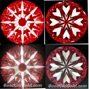
Here are H&A virtual and actual.

Sleepy... cya''ll tomorrow.

hashots.jpg
 

Rhino

Ideal_Rock
Trade
Joined
Mar 28, 2001
Messages
6,340
Date: 9/19/2005 2:54:46 AM
Author: belle

Date: 9/18/2005 11:37:23 PM
Author: Midnight
Jonathan,

Thanks for the generated H&A pics...but John and Brian might want to see the ''real'' H&A photos
2.gif
to be scientifically consistent for comparison purposes. Do you still have the original H&A photo file on this diamond to post? I only suggest to help make your presentation more complete.
yes rhino, wouldn''t it make more sense to post this with the actual h&a images since that is how brian and john are explaining it?
Yes. However in Brian/John/Bruce explanation 3 facets are twisted in the example given. This is a baby step of only one. I don''t think this would be an example of "yaw" ... just one smaller heart but I am open to listening.
 

beryl

Shiny_Rock
Joined
Nov 6, 2003
Messages
288
Rhino:
. I was away yesterday so much has occurred between your questions and my answer.
. There is no ambiguity in my answers. I sense that you do not understand what I say. I will go through it again briefly.
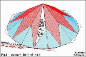
. Below is Fig.2 again. This is what you WOULD get with ONLY azimuth shift and no change in slope. Virtually nobody does this.

yaw2aa.jpg
 

beryl

Shiny_Rock
Joined
Nov 6, 2003
Messages
288
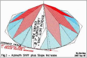
. In Fig.3 the slope of the main is increased as well so that the join between mains at the left is same as if ideally cut. This is what I think Brian calls 'yaw'; it is done by most good faceters when problems arise.
. The phantom lines show the outline of the ideally-cut facets; note that material has been removed both to the left and right of this outline.
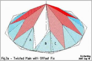
. To form a main tip at the SAME POINT on the girdle it is necessary to twist BOTH the adjoining halves(this tip will be lower than the ideal). This requires 'twisting' one clockwise and the other counter-clockwise. This is what is done in severe cases to make the stone 'look right'. In very severe cases, the second half-facet to the right (facet 'C' in Fig.3a, below) is also recut (no azimuth shift but lower slope) to raise its tip to the same level as the others. These data are provided in the exaggerated illustration of the Jan 22 pic.
. However, it is NOT NECESSARY to do this. In a case of minor 'yaw' we might recut only the half-facet on the right (B in Fig.3a) so that it met the one on the left (A in Fig.3a) at the girdle line. This is sufficient where the shift of this point on the girdle line is unnoticeable or insignificant to our eye as we cut the stone. So in this case there is no need to twist the other half.
. There is no ambiguity in my 'yes' and 'no' answers.
. Please understand that my illustrations of Jan 22 and Sep 06 are EXAGGERATED to illustrate principles; certainly the 5° and 3° azimuth shift, with 50%-deep halves, are not even close to normal deviations.

yaw3aa.jpg
 

beryl

Shiny_Rock
Joined
Nov 6, 2003
Messages
288
. Fig.3a, below, shows an offset fix, which I described above; this is all that is necessary to 'correct for' a minor twist of the main. Halves A and C are same index and slope as on a perfect cut. ONLY facet B has been twisted to accommodate the twisted main. Note that the tip of the main is now offset to the left - the scallop widths under facets A and B are unequal.
. The tips of halves B and C are lower than the others (which is 50% in this exaggerated example) because we did not reduce the slopes of B and C for this factor, but that is another matter
. So there is no ambiguity when I say that facets A and B may not both be twisted to accommodate the twisted main.

yaw3b.jpg
 

beryl

Shiny_Rock
Joined
Nov 6, 2003
Messages
288
. A major point of confusion, made evident in a comment by RocDoc, may be because I show the gem as already-cut when the main is twisted - upsetting the already-cut halves. This is not the case. In diamond-cutting the mains are all cut first, then the halves; so the adjustments I show are not by 're-cutting', as the pics and text imply, but by cutting the halves to accommodate the mains as we go along.
, As RocDoc suggests, many colored-stone cutters cut the 'breaks' ('halves' to diamantaires) first; it was not always that way. I wrote an article in late '70's, entitled 'Faceting Backwards', which described this and was considered heresy at that time; now it seems to be standard procedure among amateur colored-stone cutters.
. I apologize if this has caused confusion; it was the easiest way to illustrate the points.
 

michaelgem

Shiny_Rock
Trade
Joined
Feb 26, 2003
Messages
379
Date: 9/19/2005 2:33:19 AM
Author: Rhino
Hey Mike,


I believe, as Bruce does, that any twist, (call it yaw if you must), in the pavilion mains will have uncompensatable consequences in the face-up arrow pattern as well as the face-down hearts pattern.
Couple of questions on the brain as you say this is ...

If we twist a main on a virtual diamond will it *always* result in yaw?
If we twist a main on a real diamond will it always result in yaw?

Yes, by definition, since what Brian calls yaw is twist.

DiamCalc''s virtual diamond''s and their light performance have been established by many, including yourself, to adequately represent the optical performance of real diamonds. So the effect of twist or yaw in a real diamond can be adequately seen and analyzed, as you are doing, in DiamCalc. Michael Cowing

I''ll do it in diamcalc on the virtual and ask for Johh/Brian/Bruce''s input.
 

Rhino

Ideal_Rock
Trade
Joined
Mar 28, 2001
Messages
6,340
Date: 9/19/2005 9:33:57 AM
Author: michaelgem


Date: 9/19/2005 2:33:19 AM
Author: Rhino
Hey Mike,


I believe, as Bruce does, that any twist, (call it yaw if you must), in the pavilion mains will have uncompensatable consequences in the face-up arrow pattern as well as the face-down hearts pattern.
Couple of questions on the brain as you say this is ...

If we twist a main on a virtual diamond will it *always* result in yaw?
If we twist a main on a real diamond will it always result in yaw?

Yes, by definition, since what Brian calls yaw is twist.

DiamCalc's virtual diamond's and their light performance have been established by many, including yourself, to adequately represent the optical performance of real diamonds. So the effect of twist or yaw in a real diamond can be adequately seen and analyzed, as you are doing, in DiamCalc. Michael Cowing

I'll do it in diamcalc on the virtual and ask for Johh/Brian/Bruce's input.
Brian/John/Bruce/Paul

The hearts example posted above ... is this considered to indicate the presence of yaw? A simple yes or no will suffice, no long explanation needed. I am curious. Bruce... you have done all you can to help me and for that I am indebted to your kindness. If we are to go any further from the cutters perspective I think this would best be done over a cup of coffee (not wine cause then you'd really confuse me
3.gif
). So ... when's the next trip to Mohegan Sun?
9.gif


I can understand why Garry and other peers see this as going to a level that is a little too far out there. Slope and Azimuth are much easier to grasp and measure but I do enjoy and appreciate the dialogue taking place here. This thread has caused me to think about these things intellectually in way that no other has in a very long time.

Peace,
 

beryl

Shiny_Rock
Joined
Nov 6, 2003
Messages
288
Rhino:
. There is no need to meet to discuss it - the illustrations are better than words. If you have read everything I wrote carefully, and then the queries that I answered, and still don't get it, a meeting with me will not help. Perhaps someomne else can do it, but why? it is not important.
. I only got involved to help you (Azimuth Shift vs Yaw), then Brian and Paul (scanner profile they had asked me about - but now John says to stay out of it!). I depart these subjects now to do more important things - such as playing with my Nintendo machine, which I interrupted to write this.
. Making the pictures was fun, though. When you want illustrations, let me know.
 

JohnQuixote

Ideal_Rock
Joined
Sep 9, 2004
Messages
5,212
Date: 9/18/2005 7:58:27 AM
Author: beryl


Date: 9/17/2005 6:57:32 PM
Author: JohnQuixote

Bruce, I was the one who placed the copyright on that page, intending only to protect your work. It was a precaution only. If you prefer the copyright be removed I will do so with pleasure.
John:
. I just wanted the folks to know that I am not 'in bed' with anyone. I am a free-agent interested in helping all.
. I have been 'suspected' by appearing to be affiliated with certain parties, for defending them, or for getting credit which was not mine; this has impaired my communication with other parties.
Understood.

In case further public clarification is needed: Bruce is a contributor who has a wealth of trade experience and herculean skills at creating concise illustrations. For this he is indeed a free-agent who is to be thanked. His valued input has been impartial and voluntary - aimed only at furthering objective understanding for ALL, never tied to a particular person or interest.


Date: 9/18/2005 8:08:45 AM
Author: beryl
. I read above - but can't find it to quote - that the study of arrows was impaired by obscuration. The arrow IS CAUSED by obscuration - without it there is no arrow.
True. And if you want to track where light is being directed as it comes off the pavilion it's difficult to do so when the arrows (mains) are dark due to obscuration.


Date: 9/19/2005 6:17:08 PM
Author: beryl
Rhino:
. There is no need to meet to discuss it - the illustrations are better than words. If you have read everything I wrote carefully, and then the queries that I answered, and still don't get it, a meeting with me will not help. Perhaps someomne else can do it, but why? it is not important.
. I only got involved to help you (Azimuth Shift vs Yaw), then Brian and Paul (scanner profile they had asked me about - but now John says to stay out of it!). I depart these subjects now to do more important things - such as playing with my Nintendo machine, which I interrupted to write this.
. Making the pictures was fun, though. When you want illustrations, let me know.
This was not directed at you Bruce. And frankly, I'd rather be playing Nintendo too.
 

michaelgem

Shiny_Rock
Trade
Joined
Feb 26, 2003
Messages
379
Any twist, including that called yaw, in the pavilion mains will have uncompensatable consequences in the face-up arrow pattern.
IMO a great enough twist in lower mains will have negative effects on light performance (diamond beauty). Correct me if you think otherwise.
Systematic twists of the halves in the crown and less often in the pavilion, described by cutters and now everyone as painting and digging the halves, are another example of purposeful azimuth shifts with compensating slope adjustment to maintain the facet meet points. These twists, like twists to the mains, have observable and in some cases intended effects on a diamond cut''s optical performance and beauty. These effects, while leaving the arrow and heart patterns undisturbed do influence light performance positively or negatively depending upon your opinion.

To complete this line of thought, it seems logical and perhaps obvious that twists or yaw in the mains principally affects the arrows, while a twist or yaw in the halves, like the light leakage example from Jonathan, principally affects the areas in between. Of course that is because the arrows are reflections from the mains, and the area in between the arrows are reflections last coming off the halves (lower girdle facets).
Michael Cowing

PS I suspect, as several have opined, that the subtle twist that Brian calls yaw, has negligible observable consequences to light performance in typical illumination circumstances. Brian and John appear to believe that because it affects the heart pattern, it is evidence of less than perfect optical symmetry and craftsmanship.
Perhaps this is also true of that bit of extra light leakage at 1:30 in the middle ring of the ''eye of the diamond'' in Jonathan''s example. I wonder if it too has any observable consequences to light performance in typical illumination circumstances.
 

Rhino

Ideal_Rock
Trade
Joined
Mar 28, 2001
Messages
6,340
Date: 9/19/2005 6:17:08 PM
Author: beryl
Rhino:
. There is no need to meet to discuss it - the illustrations are better than words. If you have read everything I wrote carefully, and then the queries that I answered, and still don''t get it, a meeting with me will not help. Perhaps someomne else can do it, but why? it is not important.
. I only got involved to help you (Azimuth Shift vs Yaw), then Brian and Paul (scanner profile they had asked me about - but now John says to stay out of it!). I depart these subjects now to do more important things - such as playing with my Nintendo machine, which I interrupted to write this.
. Making the pictures was fun, though. When you want illustrations, let me know.
NINTENDO!!!
9.gif
Bruce ... ever play any online games? I love a good game of capture the flag.
1.gif


Before you depart would you be so kind as to answer my KISS question on the page prior to this? a. b. or c.?

Kind regards,
Jonathan
 

Rhino

Ideal_Rock
Trade
Joined
Mar 28, 2001
Messages
6,340
LOL... I hear Paul about this thread becoming boring. :razz: If you guys want to pick it up in pm with me that''s fine. I''ve been having some fun with DiamCalc twisting away and have generated some graphics showing the results for comparison (interesting geeky stuff to me) but if you want to let this one die I''m fine with that.

Peace out,
 

Rhino

Ideal_Rock
Trade
Joined
Mar 28, 2001
Messages
6,340
One last comment in this thread that may be of interest to some. Regarding the subject of "what a scanner sees" I can tell you from experience, the hardest thing (to my knowledge) for a scanner to see is when facets are very close in angle to their adjoining facets.

Painted upper girdles (8*, ACA new line and some unbrandeds) are a perfect example. When upper girdle angles are under 40 degrees, the closer they get to to the bezel angles the harder it is for scanners to *see* the seperation. Hence if you were to examine the models produced on these types of stones you find more problems resolving these upper half facets. Actually that is one really good test to determine the ability of a scanner.

Interestingly ... painted upper girdles will be taking a hit on the GIA system as well as upper halves that show evidence of digging (to what extent I do not know yet). Two metrics not covered in Facetware which I believe could have been if they included the input of upper girdle angles into the software.

Peace out,
 

dyemonds2002

Shiny_Rock
Joined
Aug 24, 2002
Messages
109
It sounds like it all comes together like the 8* method optical symmetry doesnt it maybe we are learning or coming close
 

Rhino

Ideal_Rock
Trade
Joined
Mar 28, 2001
Messages
6,340
Sorry but questions keep popping into my head regarding discussion here. Brain cells are expanding!

Garry ... Sergey ... you may be two of the only people I know who could answer this question that was bugging me all night.

Can you explain the optical phenomena taking place that causes those dark red reflection spikes under the table? Can this be explained and demonstrated within DiamCalc?

You guys know how long I've been studying this and that question is eating me up right now. We now know that facet twist on the lower halves contributes to leakage in an ideal cut diamond but when azimuth angles are ideal/near ideal it causes those darker reds to appear in the optical signature.

Is this double reflection thus increasing the metric of intensity? This is of intense interest to me for research purposes and I am keenly interested in hearing each of your responses.

Peace,
 

Rhino

Ideal_Rock
Trade
Joined
Mar 28, 2001
Messages
6,340
Date: 9/20/2005 8:56:34 AM
Author: dyemonds2002
It sounds like it all comes together like the 8* method optical symmetry doesnt it maybe we are learning or coming close
Oh yes dyemonds. And optical symmetry has a direct impact on diamond appearance in certain light conditions when coupled with the right proportions.
 

Rhino

Ideal_Rock
Trade
Joined
Mar 28, 2001
Messages
6,340
LOL... Mike so properly called it angst. :)

Garry ... think with me outside the box for a moment.

What do these discoveries tell us? Are you beginning to see why AGS is watching with keen interest? These scientific discoveries, through peer review lends credence to an optical analysis not fully understood yet by this industry. Are you hearing me?
 

Rhino

Ideal_Rock
Trade
Joined
Mar 28, 2001
Messages
6,340
belle ... I know you have DiamCalc. Do you know how to export to .dxf and open that .dxf and twist pavilion facets?
 

dyemonds2002

Shiny_Rock
Joined
Aug 24, 2002
Messages
109
Maye theses should diamonds should becalled Twistar hehehe
 

Garry H (Cut Nut)

Super_Ideal_Rock
Trade
Joined
Aug 15, 2000
Messages
18,461
Rhino you asked me somewhere about the intense red spikes in the ideal-scope images under the table.

If you cut and paste the brightest parts to the outside crown areas - they are not so bright - you may be confused by color contrast?
 

Rhino

Ideal_Rock
Trade
Joined
Mar 28, 2001
Messages
6,340

Hey man,


Thanks for repsonding.


Let me clarify.


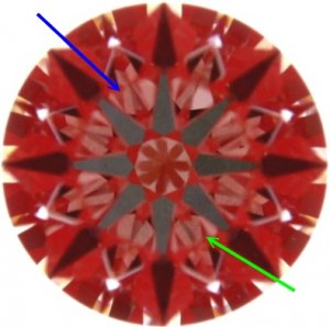
See the red spike I''m pointing to with the blue arrow? Is that a reflection of the lower half pointed to with the green arrow?


If not what?


I''ve now learned what causes the spike to twist in this example, what I want to know is what causes the spike itself.


If it''s a double reflection you''ve just taught me something about the metric of intensity and I like when that happens!


It raises more questions!!! LMAO

9.gif


Thanks in advance.


Cya tomorrow.


Rhino

Ideal_Rock
Trade
Joined
Mar 28, 2001
Messages
6,340
oops!

br133fvs2ls22.jpg
 

Garry H (Cut Nut)

Super_Ideal_Rock
Trade
Joined
Aug 15, 2000
Messages
18,461
It is nothing special Rhino - you are looking into the stone thru the table and you are seeing light that has come from the red reflector (if it is IS or ASET) - 59%.
The paler spike has a bit less than 50% light return.

It is just an interaction between lower girdle facets and crown main''s that cause the spike.

Do I need to add to the DiamCalc tutorial how to do this?
 

JohnQuixote

Ideal_Rock
Joined
Sep 9, 2004
Messages
5,212
Date: 9/21/2005 2:48:26 AM
Author: Rhino

See the red spike I''m pointing to with the blue arrow? Is that a reflection of the lower half pointed to with the green arrow? If not what? I''ve now learned what causes the spike to twist in this example, what I want to know is what causes the spike itself.

If it''s a double reflection you''ve just taught me something about the metric of intensity and I like when that happens! It raises more questions!!! LMAO
9.gif
Hey Rhino,

Before the ''Sheriff'' left town he emailed this file to me. With our equipment disconnected and stored he had a quiet moment waiting for Fed Ex to get the last packages out, which they didn’t (that’s a whole ‘nother story). He did this on his laptop for you.

First - this is not criticism of lightscope/diamxray, scanners or software. We think they are wonderful and Octonus is on top of the world with advancements in the field. What we are saying and have said from the beginning is that without the numbers provided by helium, etc. you cannot make judgments about pavilion construction from a reflector-based crown view - or any crown view. That was Brian’s point in his original coffee quiz (I bet someone can go win that Starbucks from the cutter now, as the answers are giv''n hither).

Yes, you can make determinations about light/xray/ideal/ASET images when you have a helium scan in hand. Any of us can. I’m sure Strm or Belle could school herds of tradesmen about now. But none of us can take a crown image of any flavor reflector and say for certain what’s happening in the pavilion WITHOUT the accompanying numbers. There are too many reflections.

I don’t want to go into (another) rant about crown assessment of pavilion construction – I know you’re dedicated to more listening this time around
1.gif
so check this, Sir Rhino…


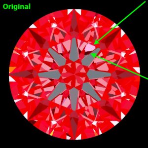
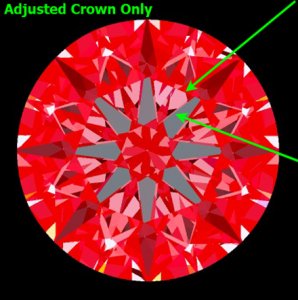
Brian took your original scanned file and made adjustments to the crown only.

He did not touch the pavilion. It remains exactly the same. Only upper girdle, crown and stars were adjusted. Your light leakage is diminished and the way things reflect and look has been changed just by altering stars and crown facets. Without a scan and accompanying numbers you would not think this pavilion and the other are the same (but they are).

br1332fvs2_Gavin.jpg
 

JohnQuixote

Ideal_Rock
Joined
Sep 9, 2004
Messages
5,212
On the other hand, you CAN make pavilion determinations with the simple and elegant hearts view. No numbers or scans required.

These things are immutable and simple. We have been saying this for about 4 threads
23.gif
It is wonderful to have technology, but just look at what Brian has done and see what’s being said. I don’t want to litter this thread with a lot more of this... Too many scans cause Wink to have a headache and some of us to play Nintendo. Brian bought a Nano and I’m afraid we might lose him if we get too far away from using the pavilion to make these determinations!
37.gif


Simply put: We believe the crown is important but the foundation is in the pavilion. If you want to do reflector assessment of pavilion construction it must be done FROM the pavilion.

When Hurricane Rita is all over we’ll return to comment more.


PS: Brian asked me to send the adjusted dmc file to Garry for verification in case you think he might have adjusted anything besides the crown... Thems cutters is tricky.
 

strmrdr

Super_Ideal_Rock
Joined
Nov 1, 2003
Messages
23,295
John,
You have more important things to worry about but I wanted to post this while I was thinking about it.
Can you please post the hearts image for the twisted crown virtual diamond.
By Brian''s definition is it yaw if its the crown and not the pavilian thats shifted?
 
Status
Not open for further replies. Please create a new topic or request for this thread to be opened.
Be a part of the community Get 3 HCA Results
Top