- Joined
- Sep 3, 2000
- Messages
- 6,745
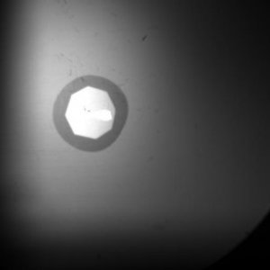
This is the image of an actual diamond that I own. It is not perfectly round, as you can readily see by the dark outer outline, and even has a bit of a flat spot on one side, as you can see in the photo of it taken from the top view. It is not an exceptional diamond or a super fine stone, but it is a regular, commercial cut diamond. When measures of diameter are taken with this top view one can see indentations or flat places clearly. If one was to ask for a 3D model of this stone in one of the drawing programs generated from a Sarin, Ogi, or Helium device, would the rendering in 3D handle this correctly? Since the side view approach taken by the devices mentioned is what is utilized and not a top view, the flat spot is far less likely to be exactly detected. These devices do not take an infinite number of views, but only every few degrees. Who is to say if a flat was exactly viewed or a bit of the curved part ahead or behind the flat spot was measured?
We believe this diamond is an excellent example of a basic problem with using a side image for obtaining correct diameter and correct table measures. The side view may get the maximum diameter most of the time, but it may fail to determine the actual minimum diameter a great deal of the time. The minimum diameter will be over-estimated most of the time.
When one over-estimates the minimum diameter, the average diameter is also increased. Following that error, a subsequent error then occurs. The table percentage calculation for a 3D model or a grading report then becomes a smaller percentage than the actual percentage. Any ray tracing calculation would also skewed from these combined errors.
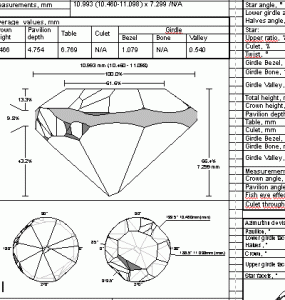
Going further, the question arises how does this side view method do the job with table measurement? A table has 8 flat sides and 8 points (junctions). Table diameter is measured from one point to its opposite point. In effect, it is four maximum table widths. In the failure to exactly be able to visualize the flat sides there is a corresponding inability to be certain the maximum widths of the table (the opposite points) are equidistant from the lens when the measure is taken. Therefore, the table measure may often be underestimated. This leads to a second reason for underestimating the correct table percentage.
ImaGem was been asked why its reported table percentages are somewhat larger than other methods. This should clear the air on that topic. The side view method does not consistently see the minimum diameter nor the maximum table width.
What should be of even greater concern than a percent or two in table diameter or a tenths or two mm difference in minimum, maximum and average diameter, is what seems an unscientific, more or less blind, acceptance of the improper measures in creation of light handling models. Substantial error in measurements will result in flawed calculation of light performance. There is no way around this fact when using a side view.
Going into the future, how will a side view ever measure the cleft of a diamond such as found in a heart shape? This is even more of a problem than just a flat spot on a round shape. Any out of roundness that actually indents cannot be viewed from a side view at all. A flat spot may only be correctly measured occasionally, but not with the consistency one would expect of such high cost devices.
Without an ability to model such common diamonds correctly, how can we just rely on the calculation of light performance? A flat or an indenting diamond cut defect is far more noticeable than any yawed facet might be, and it seems logical it must create a light return issue of greater magnitude, too.
Has anyone addressed this issue in some way that I have missed? Are there any comments?


300x240.png)