shape
carat
color
clarity

Optimal AGSL Light Performance Map Question-Area above Culet

starryeyed

Ideal_Rock
Joined
Nov 6, 2006
Messages
2,398
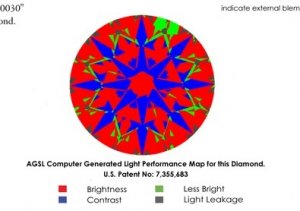
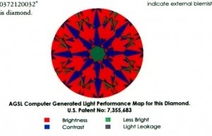
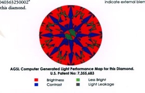
When looking at the WF ACA RB diamonds, I noticed that the center area above the culet on almost every AGSL Computer Generated Light Performance Map (on Platinum Diamond Quality Documents) differs. The center area can be red, green, or a combination of both.

Of course I understand that every diamond is different, but what does this mean in terms of visual appeal of a stone? Is it a personal preference sort-of-thing or are diamonds that are all red in the center more visually appealing?

I'm attaching a few images from different PDQD's.
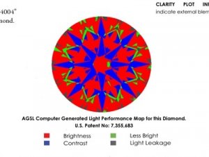
AGS Perf Map 1.jpg

AGS Perf Map 2.jpg

AGS Perf Map 3.jpg

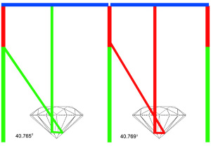
AGS Perf Map 4.jpg
 
Re: Optimal AGSL Light Performance Map Question-Area above C

starryeyed said:
what does this mean in terms of visual appeal of a stone?

It's a table-reflection dynamic. No visible difference.

Explained: At a pavilion angle average of 40.768 degrees or above the table-reflection area in the center of the diamond is receiving light from 45 degrees, which is the red area of the ASET. When the pavilion angle average decreases to less than 40.768 degrees the table reflection area now receives its light from below 45 degrees; the green area of the ASET. When some of the pavilion mains are above and others are below that 40.768 mark you get a mixed look. AGSL has nicknamed such diamonds "on the ledge."

file.jpg

I would add that different ASET setups can influence precisely where the "ledge" is (+/- 40.768)

Here's my original 2005 thread and discussion on the subject.
https://www.pricescope.com/communit...-768-pavilion-on-the-ledge.29977/?hilit=ledge
 
Re: Optimal AGSL Light Performance Map Question-Area above C

John Pollard said:
starryeyed said:
what does this mean in terms of visual appeal of a stone?

It's a table-reflection dynamic. No visible difference.

Explained: At a pavilion angle average of 40.768 degrees or above the table-reflection area in the center of the diamond is receiving light from 45 degrees, which is the red area of the ASET. When the pavilion angle average decreases to less than 40.768 degrees the table reflection area now receives its light from below 45 degrees; the green area of the ASET. When some of the pavilion mains are above and others are below that 40.768 mark you get a mixed look. AGSL has nicknamed such diamonds "on the ledge."

file.jpg

I would add that different ASET setups can influence precisely where the "ledge" is (+/- 40.768)

Here's my original 2005 thread and discussion on the subject.
https://www.pricescope.com/communit...-768-pavilion-on-the-ledge.29977/?hilit=ledge

Great explanation Jon. Just to add as the differences to change the color in the mains in that area are in tenth of a degree or less, so scanning error can change red to green on the AGS report even though the angle of the mains could still be 40.8 or above. If the scanning error could be as much as +/- 0.2 degrees the actual value would be 40.8 +/- 0.2 so the color in that region is even less relevant.
 
Re: Optimal AGSL Light Performance Map Question-Area above C

Hi John. Nice to see you - thanks for the link.

That discussion was pretty thick, so it wasn't all clear to me. I'm sorry to be dense, but I'm still confused about WHY Red is no better than Green in the "eye". Maybe I'm not clear about the diagram. I thought the more Red the better.

You mentioned that AGS is doing some interesting work regarding dispersion and that: "I do think we will revisit this as AGS moves forward in the development of their baseline for a meaningful measure of scintillation."

Have there been any recent developments? At least something little ol' me can understand. ::)
 
Re: Optimal AGSL Light Performance Map Question-Area above C

It is at the arbitrarily decided junction between color code that AGS decided to use.

The light comes almost from the same location, so in real life it is as good as the same.
 
Re: Optimal AGSL Light Performance Map Question-Area above C

starryeyed said:
Hi John. Nice to see you - thanks for the link.

That discussion was pretty thick, so it wasn't all clear to me. I'm sorry to be dense, but I'm still confused about WHY Red is no better than Green in the "eye". Maybe I'm not clear about the diagram. I thought the more Red the better.

You mentioned that AGS is doing some interesting work regarding dispersion and that: "I do think we will revisit this as AGS moves forward in the development of their baseline for a meaningful measure of scintillation."

Have there been any recent developments? At least something little ol' me can understand. ::)

Starryeyed,

I am not Sir John, but I do aspire to be as good an educator as he has demonstrated over the years.
The most recent AGS presentations by Peter Yantzer on scintillation(sparkle) and dispersion(colored flashes) did not provide any correlation to a change in these two properties as a result of slight changes in the pavilion angle at or near ideal tolk round proportions.

All of this to say that whether the eye is red or green in the ASET is not an indicator of lessor or greater performance particularly when considering stones at or near this color boundary.
 
Re: Optimal AGSL Light Performance Map Question-Area above C

Thanks starryeyed

starryeyed said:
I'm sorry to be dense, but I'm still confused about WHY Red is no better than Green in the "eye". Maybe I'm not clear about the diagram. I thought the more Red the better.

Not dense at all. It's a good question.

StoneCold explained how, since the light is drawn from virtually the same location, it's minutiae. I think it's also important to understand what "table reflection" is:

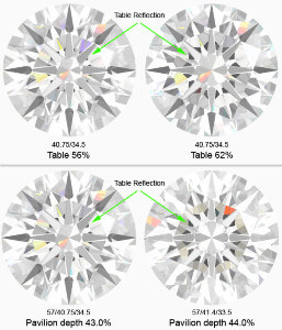
Unlike the other parts of the ASET image, that small circle over the culet is not primary light return. What you are seeing is a reflection (in the bottom of the stone) of the underside of the table facet... Imagine that you are inside the diamond looking up. What do you see? The large, flat table facet reflecting back down on you like a mirror - and since you're a reflective surface yourself you re-reflect that reflection back up again. So what we're seeing from above, in this static situation with controlled lighting, is a tiny reflection-of-a-reflection. When the diamond leaves our static, magnified lab view and goes in-motion, in normal lighting, at normal viewing distances it's a non-factor - especially in diamonds like this where the difference in whether you see green/red/mix is arbitrary minutiae.

It may be useful to know that diamond cutters have used the phenomenon of table reflection to judge pavilion depth since long before we had tools or 3D scanners capable of measuring tenths of degrees. It's how Lazare Kaplan and such diamantaires reliably crafted their desired proportion sets many decades ago.

While we're on the topic, table reflection can become an issue in diamonds with larger tables or deeper pavilions, where the reflection becomes larger and strays outside the above-culet area. No worries; such makes are typically outside the range of fine-makes consumers typically bring up on Pricescope, but it's worth mentioning. The graphic below shows how the table reflection footprint increases as table size and/or pavilion depth increase. Of course these graphics are "perfect" wireframe simulations. In real diamonds, especially poorer makes, a level of asymmetry can 'bloat' the reflection's appearance making it more dramatic. This is something we would look for in lab/diffused lighting. It is not as notable in normal viewing, especially when the diamond is in motion.

file.jpg
 
Re: Optimal AGSL Light Performance Map Question-Area above C

ChunkyCushionLover said:
Starryeyed,

I am not Sir John, but I do aspire to be as good an educator as he has demonstrated over the years.

The most recent AGS presentations by Peter Yantzer on scintillation(sparkle) and dispersion(colored flashes) did not provide any correlation to a change in these two properties as a result of slight changes in the pavilion angle at or near ideal tolk round proportions.

All of this to say that whether the eye is red or green in the ASET is not an indicator of lessor or greater performance particularly when considering stones at or near this color boundary.

Thanks Jordan. Meanwhile, I wish my daily attendance was as good as yours.

This concurs with what I've studied and followed since 2005: Research of scintillation and dispersion - particularly the importance of virtual facets, the nature/visibility of dispersive "fans" and the implications symmetry/crispness have - kind of blow side-phenomena like this away. Much advancement in the past five years, and we're still just swimming on the surface.
 
Re: Optimal AGSL Light Performance Map Question-Area above C

Thanks John. Understanding table reflection is what I was missing. I think I get it now! ::)

Hope you love your new job!
 
Re: Optimal AGSL Light Performance Map Question-Area above C

I found this very helpful and informative as well. Thank you so much!
 
Re: Optimal AGSL Light Performance Map Question-Area above C

John Pollard said:
ChunkyCushionLover said:
This concurs with what I've studied and followed since 2005: Research of scintillation and dispersion - particularly the importance of virtual facets, the nature/visibility of dispersive "fans" and the implications symmetry/crispness have - kind of blow side-phenomena like this away. Much advancement in the past five years, and we're still just swimming on the surface.

I await the day when AGSL will be able to go beyond the status quo of smaller more frequent flashes versus larger slower ones
being a personal preference for scintillation. I beleive the two will always be inversely correlated but with proper design you can increase the average virtual facet size without slowing down scintillation. Karl K has touched on this area but thus far I haven't seen anything conclusive by any authority on the topic. One thing is very clear to me though, this property cannot be properly simulated or measured using ASET structured lighting.
 
Re: Optimal AGSL Light Performance Map Question-Area above C

ChunkyCushionLover said:
....but with proper design you can increase the average virtual facet size without slowing down scintillation. Karl K has touched on this area but thus far I haven't seen anything conclusive by any authority on the topic. One thing is very clear to me though, this property cannot be properly simulated or measured using ASET structured lighting.
I'd love it if Karl K could chime in. What kind of design and for what kinds of effects? In easy language for my simple mind, please.
 
Re: Optimal AGSL Light Performance Map Question-Area above C

starryeyed said:
ChunkyCushionLover said:
....but with proper design you can increase the average virtual facet size without slowing down scintillation. Karl K has touched on this area but thus far I haven't seen anything conclusive by any authority on the topic. One thing is very clear to me though, this property cannot be properly simulated or measured using ASET structured lighting.
I'd love it if Karl K could chime in. What kind of design and for what kinds of effects? In easy language for my simple mind, please.

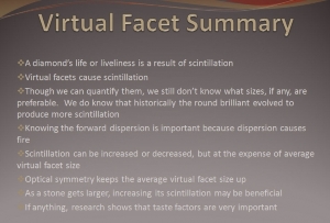
From Peter Yantzer(Executive Director, AGS Laboratories) Where We Are and Where We’re Going - REDUX April 11 & 12, 2010
PeterYantzerApril11&12Scintillation.jpg
 
Re: Optimal AGSL Light Performance Map Question-Area above C

Thanks CCL - not sure what forward dispersion is, nor virtual facets.
 
Re: Optimal AGSL Light Performance Map Question-Area above C

starryeyed said:
Thanks CCL - not sure what forward dispersion is, nor virtual facets.

Forward Ray Tracing - From the source redirected through the diamond to the the eye of the viewer.

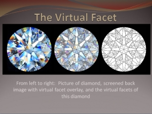
Here is a diagram of what virtual facets are from PY again.

THEVFPeterYantzerApril2010.jpg
 
GET 3 FREE HCA RESULTS JOIN THE FORUM. ASK FOR HELP
Top